Single-pulse DC control for electrocatalytic reactor systems
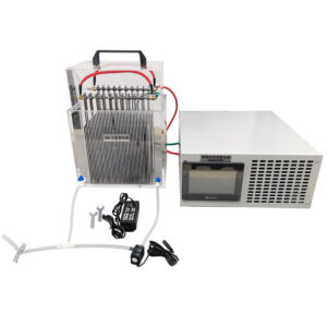
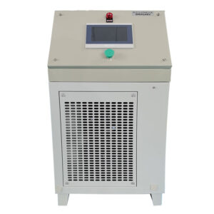
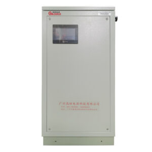
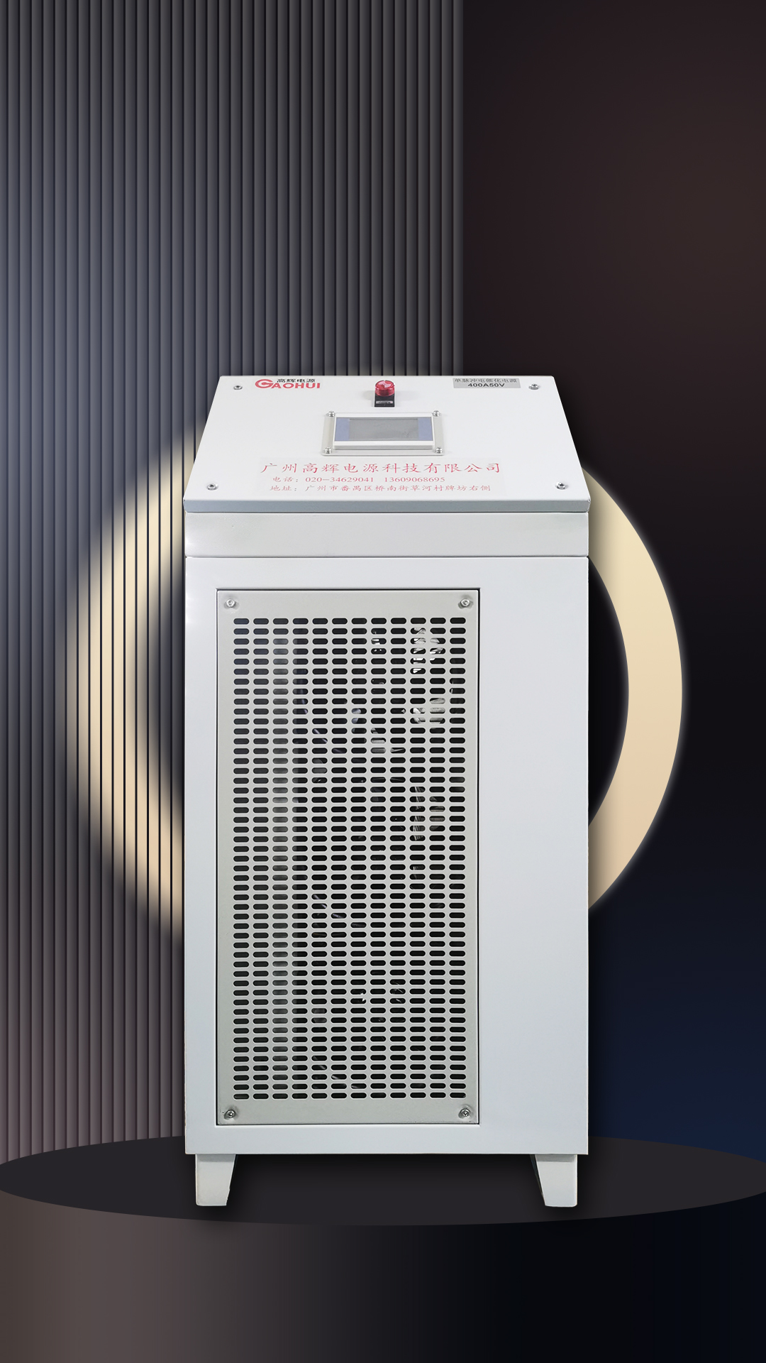
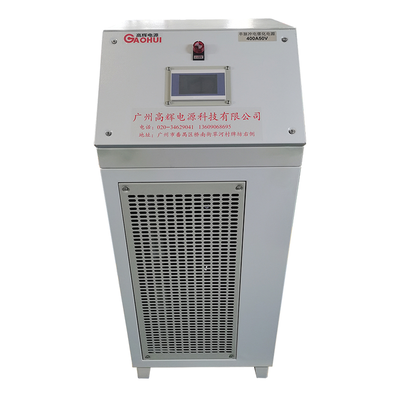
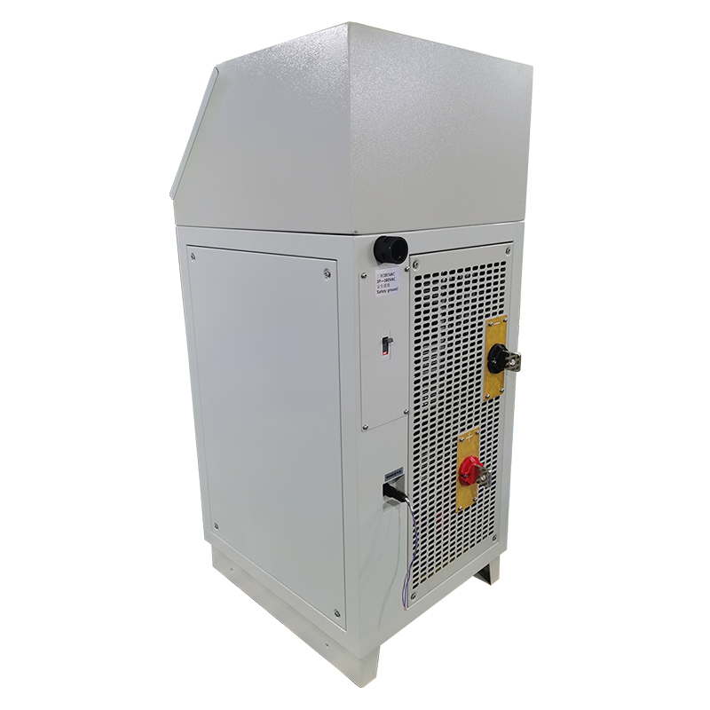
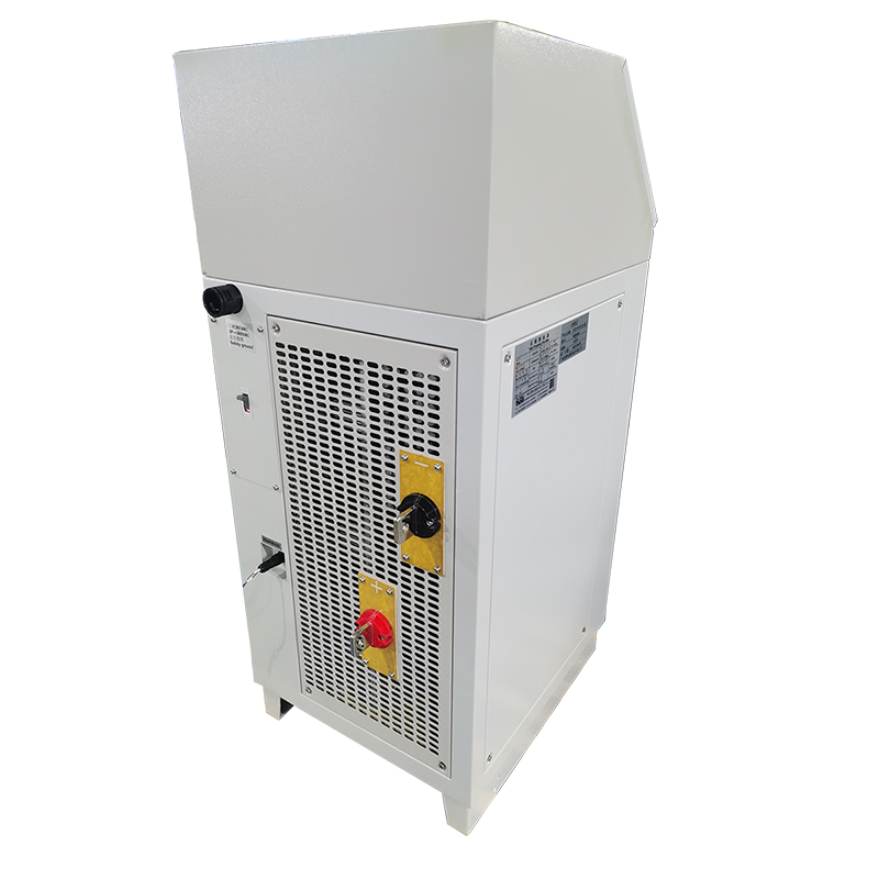
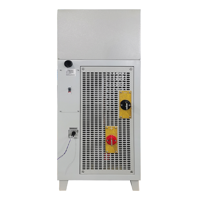
This 400A 50V single-pulse rectifier is configured for electrocatalytic oxidation equipment that needs a controlled DC supply for an electrode reactor. The rectifier connects to the positive and negative electrode circuits, while the HMI provides a local point for setting and reviewing the main operating values.
The pulse arrangement, electrode configuration, reactor volume and operating duty should be considered together. They influence the selected output range, conductor arrangement, cooling space and the control signals needed between the rectifier and the treatment skid.
Key functions for pulsed electrocatalytic systems
- Single-pulse output: a pulse-capable DC configuration for applications that specify a single-pulse operating approach.
- Adjustable DC range: set output current within 0–400A and output voltage within 0–50V.
- Constant-current or constant-voltage operation: select the control mode required by the reactor and process design.
- HMI parameter control: centralise key process settings and output readings at the cabinet.
- Operating status information: view output values and program-related status information at the local interface.
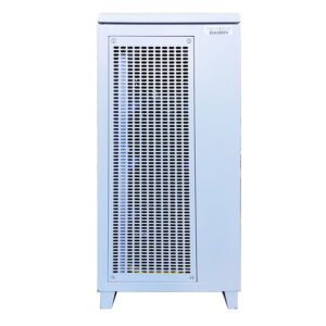
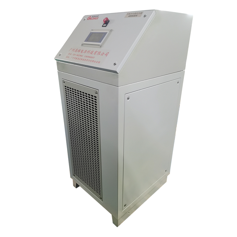
- Forced-air cabinet cooling: three-fan air-cooled cabinet construction for installations with appropriate ventilation clearance.
Configuration reference
| Item | Reference for this configuration |
|---|---|
| DC output voltage | 0–50V adjustable |
| DC output current | 0–400A adjustable |
| Output approach | Single pulse, configured for the project |
| Typical process | Electrocatalytic oxidation |
| Local interface | HMI touchscreen control terminal |
| Cooling | Forced air, three-fan cabinet |
| Cabinet form | Vertical cabinet |
| Approximate dimensions | 510 × 580 × 1190mm |
| Approximate weight | 135kg |
How the rectifier connects to a treatment skid
The DC output is matched to the reactor electrode terminals according to the electrical drawing. A system may also need start/stop, alarm feedback or interlock signals between the rectifier and pumps, flow equipment or other skid controls. The required terminals and sequence should be defined before the final configuration is released.
For other pulsed DC configurations, see the pulse rectifier range. If the project needs a different electrocatalytic output range, compare the 150A 30V electrocatalytic oxidation rectifier.
Inputs that help define the final configuration
Please provide the reactor voltage and current target, electrode arrangement, pulse requirement, operating schedule, available AC supply, cooling environment, conductor layout and any external signals. These details allow the output, control and connection arrangement to match the actual equipment rather than a generic installation.
What does single-pulse mean for this rectifier?
It identifies the required pulse-output approach. The final pulse program and operating settings are configured around the reactor and project requirements.
Can the output current and voltage both be adjusted?
Yes. This configuration provides adjustable output from 0–400A and 0–50V, with constant-current or constant-voltage operating modes available for the selected setup.
Can the HMI connect with external equipment controls?
The local interface can be configured around the project control scheme. Required start/stop, alarm and interlock signals should be identified with the treatment skid drawing.