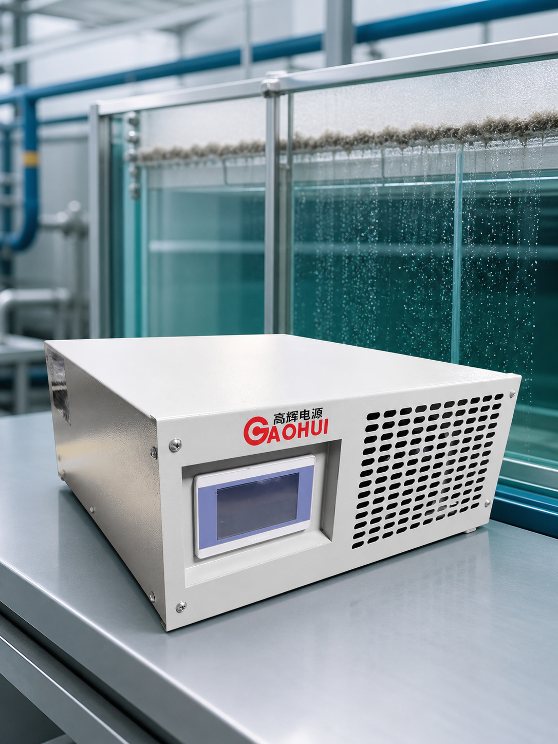
Electroflotation separates suspended material by generating very fine gas bubbles directly at submerged electrodes. Those bubbles attach to particles and carry them toward the surface for removal. The power supply controls the electrical conditions that create the bubbles, but the result also depends on water conductivity, electrode geometry, residence time and the skimming system.
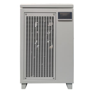
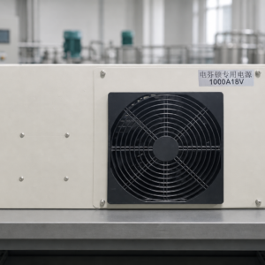
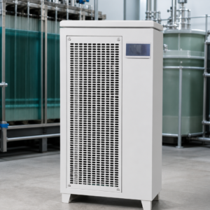
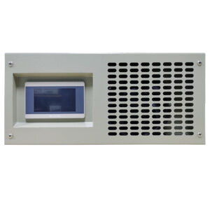
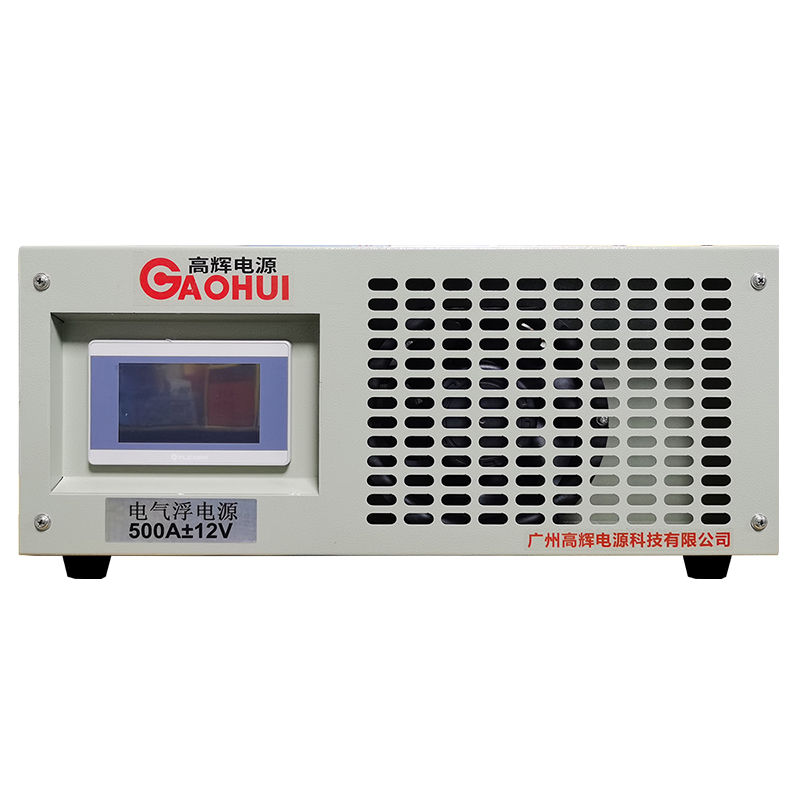
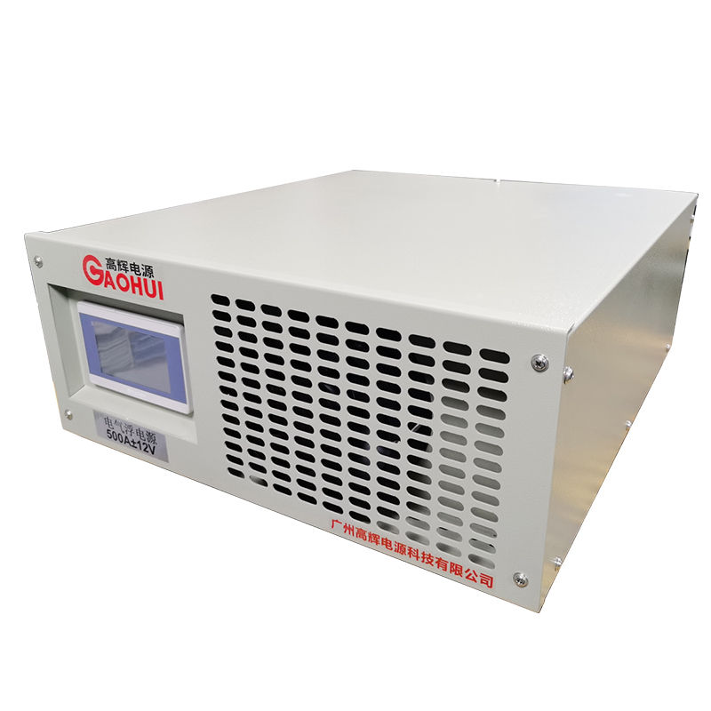
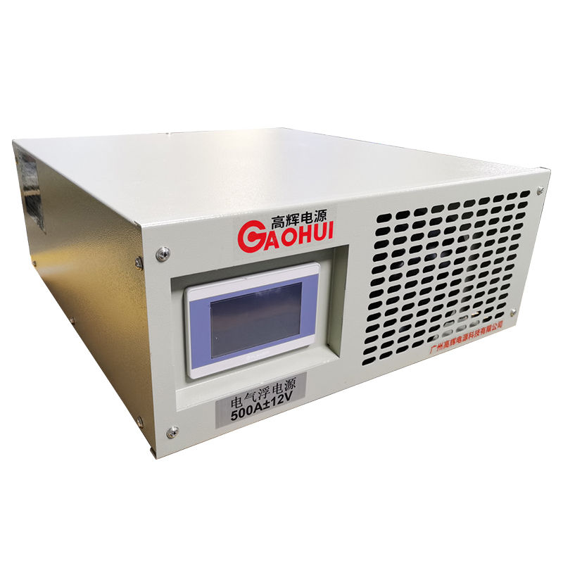
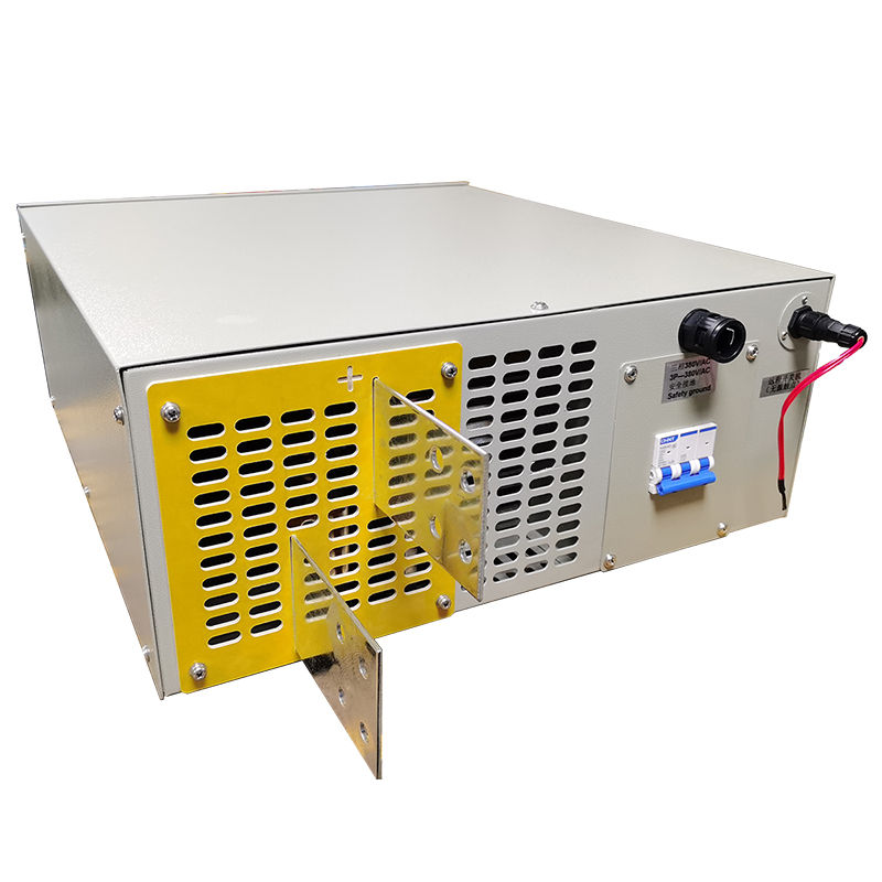
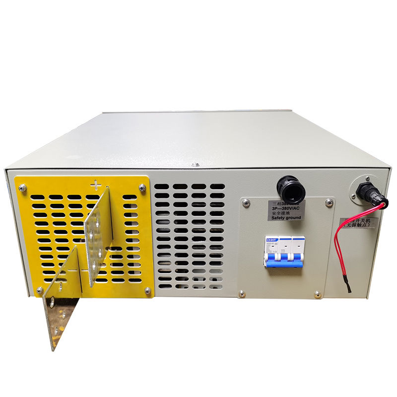
This compact 12V 500A rectifier is intended for low-voltage, high-current electroflotation equipment. Its horizontal enclosure can be installed on a floor support or equipment rack close to the treatment skid, while the touch interface provides straightforward local adjustment.
Designed for a bubble-generating electrical load
Electroflotation is not the same as dissolved-air flotation. It does not rely on releasing pressurized dissolved gas through a recycle loop. It is also not automatically the same as electrocoagulation, where sacrificial electrode dissolution and floc formation may be the primary objective.
In an electroflotation cell, current density influences gas generation at the electrode surface. Too little current may produce insufficient bubbles for the hydraulic load. Excessive current can increase energy use, heating and gas evolution without improving separation in proportion. A useful rectifier must therefore provide an adjustable, stable operating range rather than one uncontrolled maximum output.
Reference configuration
| Item | Reference configuration |
|---|---|
| Rated DC output | 0–12 V, 0–500 A |
| Rated DC power | 6 kW |
| Typical AC input direction | Three-phase 380/415 V |
| Cooling | Forced-air cooling |
| Local operation | 4.3-inch touch interface |
| Installation | Horizontal, floor or rack support |
| Approximate enclosure | 510 × 580 × 230 mm |
| Approximate weight | 37 kg |
The reference output does not define the process capacity by itself. Final selection must consider effective electrode area, electrical connection and the water’s worst expected conductivity.
Connecting the rectifier to the flotation cell
The positive and negative DC outputs connect to the electrode busbars using cables or copper bars sized for the continuous current and installation distance. The cell should have reliable liquid-level and circulation conditions before output is enabled.
Gas evolution also requires appropriate ventilation. Depending on the system design, the rectifier can exchange permissive, run and alarm signals with the skid controller so that electrical output stops when a critical flow, level or extraction condition is lost.
Constant-current control is often useful because it maintains the selected electrical loading as cell resistance changes. However, the final control mode should follow pilot data and the process designer’s operating strategy.
A better way to size the output
Start with the effective electrode area and the current density demonstrated by testing. Then check whether the cell voltage remains within the rectifier range across:
- Minimum and maximum wastewater conductivity
- Clean and aged electrode conditions
- Expected electrode gap and immersion depth
- Series, parallel or mixed electrical connection
- Normal operating temperature
- The longest required treatment cycle
If voltage readings are not available, a short pilot run under representative water conditions provides much stronger evidence than estimating from flow rate alone.
Other low-voltage electrochemical configurations can be reviewed in our wastewater rectifier category. If the primary mechanism is electrode dissolution and floc formation, compare the requirements with an electrocoagulation rectifier before selecting the control range.
Details required for a quotation
- Treatment objective and solids-removal method
- Electrode material, quantity, effective area and gap
- Cell connection diagram and busbar arrangement
- Wastewater conductivity, pH and temperature range
- Target current density or measured test current
- Normal cell voltage and highest observed voltage
- Batch or continuous flow, residence time and skimming method
- Ventilation, liquid-level and flow interlock requirements
- Available AC supply and preferred remote-control signals
Frequently asked questions
Will a larger current always create better flotation?
No. More current generally increases gas generation, but separation also depends on bubble size, particle properties, mixing, hydraulic retention and surface removal. The operating point should be established through process testing.
Is polarity reversal required?
Not in every electroflotation system. Reversal may be used for a specific electrode-management strategy, but it should not be added without confirming its effect on the intended reactions.
Can the unit be mounted on a wall?
This enclosure is intended to sit horizontally on a stable floor support or equipment rack. Installation should leave enough clearance for air intake, exhaust and cable routing.
Discuss your cell before fixing the rating
Send the electrode drawing, conductivity range, pilot current and voltage, treatment cycle and control requirements. We can then check whether 12V 500A provides the correct working envelope and prepare a rectifier interface for the complete electroflotation skid.