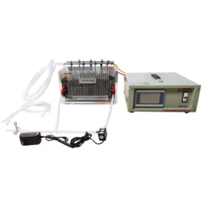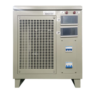
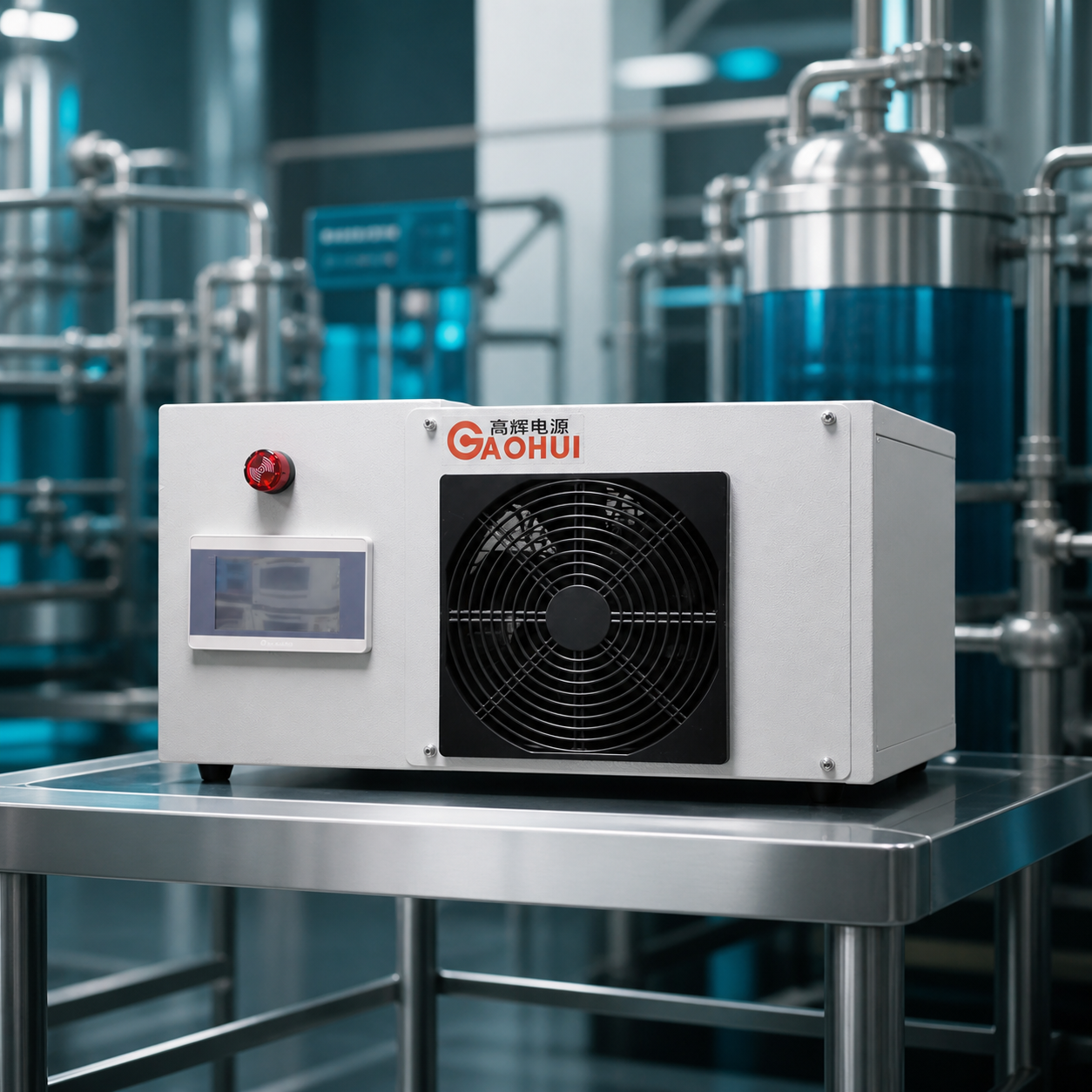
Three-dimensional electrocatalytic reactors can present a different electrical load from a simple plate-electrode cell. The electrode bed, reactor geometry, conductivity, and hydraulic condition can all affect the operating voltage. This 300A 40V rectifier is designed for projects that need a wider DC voltage range while retaining controlled current for an electrocatalytic oxidation reactor.
Its DC outputs connect to the reactor’s positive and negative electrode circuits. The power supply is configured alongside the reactor, pumps, interlocks, and process controller rather than treated as a standalone treatment unit.
Typical Build Direction
| Item | Configuration |
|---|---|
| Adjustable DC output | 0–40 V, 0–300 A |
| Rated output power | 12 kW |
| AC input | Three-phase AC 380 V or 415 V, confirmed for the project |
| Regulation mode | Selectable constant-current or constant-voltage operation |
| Cooling | Forced-air cooling |
| Local control | 4.3-inch control interface |
| Enclosure direction | Horizontal industrial enclosure |
| Approximate enclosure size | 520 × 570 × 290 mm |
| Approximate weight | 40 kg |
| Intended process | Three-dimensional electrocatalytic oxidation |
Final input, terminals, protection settings, enclosure detail, cable entry, and control interface are confirmed for the installed reactor and available site supply.
Why a 40 V Range Matters in Three-Dimensional Electrocatalysis
In a three-dimensional reactor, the effective electrical path can be influenced by the gap between primary electrodes, the conductive particle bed, water conductivity, reactor fouling, and the number of treatment cells. A system that begins at a lower cell voltage may require more voltage as the operating condition changes.
The 0–40 V range gives the system designer practical headroom to accommodate the reactor load without selecting voltage blindly. The required rating should still be based on measured or estimated operating voltage at the required current, including DC cable and busbar losses.
For lower-current or higher-voltage comparisons, see the electrocatalytic oxidation rectifier range. A 150A 30V electrocatalytic oxidation rectifier may suit a smaller reactor load, while a 250A 120V electrocatalytic oxidation rectifier is designed for a substantially wider voltage requirement.
Connection to the Treatment Reactor
The AC supply enters through the project distribution and protection equipment. The rectifier’s DC positive and negative outputs connect to the designated anode and cathode busbars or electrode terminals of the reactor. DC cable size, terminal material, polarity, and cable route should be selected to control voltage drop and suit the treatment environment.
Run permission can be coordinated with circulation pumps, liquid level, flow, ventilation, or other process interlocks. The rectifier supplies controlled DC power; it does not replace the reactor vessel, electrode media, hydraulic design, oxidation chemistry, downstream separation, or safety controls.
Selecting Current and Voltage
Current selection starts with the active electrode area, reactor design, target current density, and treatment duty. Voltage selection is then verified from the actual reactor load. Conductivity, electrode spacing, particle-bed condition, temperature, process flow, and cell arrangement can change the voltage required at a given current.
Provide the following data for selection:
- Reactor drawing, electrode arrangement, and effective electrode area
- Primary electrode material and particle-bed or packing information where applicable
- Target current density, flow rate, and operating hours
- Measured or estimated operating voltage at target current
- Conductivity, temperature, pH, and expected water-quality variation
- Available AC supply, installation space, and ambient conditions
- Required local controls, remote commands, alarms, or communication
Control and Construction Options
The rectifier can be configured with a local touchscreen, remote enable, current or voltage command, run and alarm feedback, and selected industrial communication interfaces. Constant-current or constant-voltage mode is selected for the operating strategy; both are not assumed to run simultaneously.
Automatic polarity reversal is not listed as a standard function for this configuration. It can only be evaluated when the reactor design and operating method explicitly require it. For a higher-current low-voltage alternative, review the 750A 24V electrocatalytic oxidation rectifier.
Frequently Asked Questions
Why would a three-dimensional reactor need more voltage than a simple plate cell?
The conductive path through a packed or particle-assisted reactor can add resistance and can change with water conductivity, loading, hydraulic condition, and the state of the electrode bed. The final voltage range should therefore be verified at the intended operating current.
Does 300A 40V guarantee a particular COD or color reduction result?
No. It defines the power supply operating range. Treatment performance depends on the wastewater, oxidation process, reactor design, electrode and packing material, current density, residence time, chemistry, and downstream treatment steps.
Which control mode is normally used for this reactor?
Constant-current control is often useful when the process is managed around current density. Constant-voltage control can be useful during commissioning or under a specific system strategy. The correct mode is selected from the reactor operating plan.
Can this rectifier connect to more than one reactor module?
It can be considered when the electrical connection plan is defined. Series modules increase voltage demand; parallel modules increase current demand and require appropriate current-sharing and busbar design.
What information is needed before the final configuration is confirmed?
Provide the reactor electrical data, target operating point, expected load variation, AC input, required duty cycle, installation conditions, and control-interface list. These details determine the final DC range, cooling, terminals, protections, and control arrangement.
Discuss Your Reactor Configuration
Send the reactor electrical data and treatment duty to discuss a suitable DC range, input arrangement, cooling method, enclosure, terminals, and controls for your three-dimensional electrocatalytic oxidation system.