
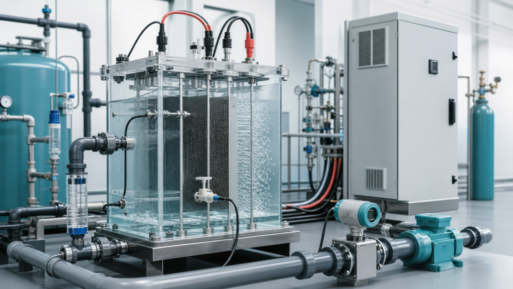
The first question in an electro-Fenton power-supply project is often, “How many amps do we need?” It is an important question, but it comes too early if the reaction route and electrode geometry are still undefined.
Electro-Fenton can describe several related systems. One reactor may generate hydrogen peroxide at an oxygen-fed cathode. Another may use electrical current mainly to regenerate ferrous ions. A third may combine those functions with anodic oxidation. These routes can place different demands on electrodes, gas delivery and control.
A useful rectifier specification begins with the reactor—not a standard ampere-per-cubic-meter rule.
Start with the electrochemical route
Document what each electrode is expected to do. If the cathode generates hydrogen peroxide, the oxygen-transfer method and cathode structure are central design inputs. If iron regeneration is the main function, iron source and redox conditions need equal attention. If anodic oxidation contributes to treatment, anode material and potential limits may influence the electrical window.
This definition also prevents inappropriate features from entering the specification. For example, automatic polarity reversal is not automatically beneficial. Reversing the electrodes may alter the intended chemistry rather than simply clean the cell.
Estimate current from effective electrode area
For an initial design, current is linked to current density and effective area:
Current = current density × effective electrode area
The “effective” area is the portion that actually participates under the proposed immersion and flow conditions. Total plate area can overstate the useful value if part of the surface is outside the liquid, shielded or poorly supplied with reactants.
The target current density should come from representative tests, published process development used with caution, or an experienced reactor designer. It cannot be selected from wastewater flow alone. The same flow rate can require very different electrical input when COD composition, conductivity, pH, oxygen transfer and reaction time change.
Treat cell voltage as a variable
The rectifier does not impose an arbitrary process voltage. It provides enough voltage to drive the selected current through the complete electrical load.
That load includes reaction potentials, electrode overpotential, solution resistance, contacts and cables. In the water, resistance changes with conductivity, temperature and electrode gap. Surface condition also matters: deposits, gas coverage and electrode aging can raise the voltage needed to maintain current.
Collect cell-voltage readings under at least three conditions when possible:
- Representative water at the start of a run
- The lowest expected conductivity or coldest valid condition
- An aged or end-of-cycle electrode condition
The rectifier needs reasonable voltage margin above the highest valid operating point, while retaining good adjustment around the normal point.
Include oxygen supply in the electrical discussion
For cathodic hydrogen peroxide generation, current alone cannot compensate for inadequate oxygen at the reaction surface. Increasing current beyond the mass-transfer capability can reduce efficiency and promote unwanted reactions.
Record the oxygen source, delivery pressure or flow approach, cathode structure, circulation pattern and interlock philosophy. The electrical start sequence may need an oxygen or air permissive before current rises. Loss of gas or flow may require controlled output shutdown.
Choose control functions that match the operating cycle
Constant-current control is often valuable because the electrochemical production rate is closely related to current. Voltage limiting still matters because it identifies an abnormal or out-of-range load.
Batch systems may benefit from timed recipes, remote start/stop and ampere-minute tracking. Continuous systems may need an external setpoint from a PLC and alarm feedback. Multiple cells may justify separate channels if their loads must be controlled independently.
Pulse operation should be specified only when process evidence supports it. Adding a feature to the front panel does not prove that it improves treatment.
A practical sizing checklist
Before requesting a rectifier quotation, assemble:
- Electro-Fenton route and treatment objective
- Electrode materials, effective areas and polarity roles
- Electrode gap, immersion and series/parallel connection
- Conductivity, pH and temperature range
- Target current density and treatment time
- Pilot current and cell-voltage trend, if available
- Oxygen or air-delivery method
- Batch or continuous control sequence
- Required PLC signals, alarms and communication
- Available AC input, cable distance and installation environment
For a concrete reference, the 1000A 18V electro-Fenton rectifier shows a low-voltage, high-current configuration with remote timing control. It is an output example, not a universal prescription. Other voltage and current envelopes can be compared in the electrochemical wastewater rectifier range.
Frequently asked questions
Can I size an electro-Fenton rectifier from reactor volume?
Not reliably. Volume and flow help define treatment time, but current depends more directly on electrode area, current density and the chosen reaction route.
Should I select extra voltage for safety?
Some margin is sensible, but excessive range is not a substitute for load data. Measure or estimate the worst valid cell voltage and then apply a justified engineering margin.
Which matters more, current or voltage?
Current often tracks the electrochemical reaction rate, while voltage is what the supply must provide to push that current through the changing load. Both are necessary for selection.
What data is most valuable from a pilot test?
Record current, cell voltage, conductivity, pH, temperature, oxygen conditions, treatment time and water-quality response throughout the run—not only the final result.
The right specification is a shared boundary
The process designer defines the reaction and valid operating window. The rectifier manufacturer turns that window into controllable electrical hardware, cooling, protection and interfaces. Bringing those two sides together early produces a more useful specification than simply ordering the largest available current rating.