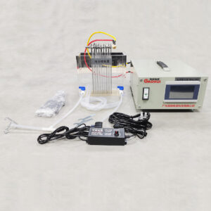
Electrodialysis reversal uses controlled changes in DC polarity to support membrane-stack operation and electrode maintenance strategies. The rectifier supplies the electrical sequence, while membrane area, stack arrangement, feed conductivity, flow and process timing determine the operating window.
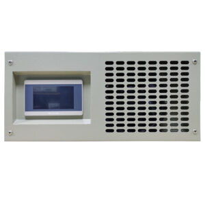
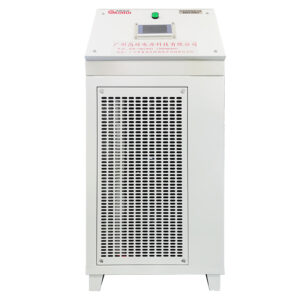
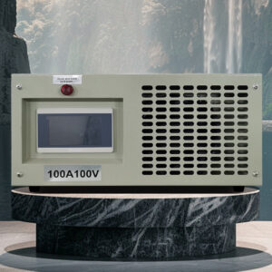
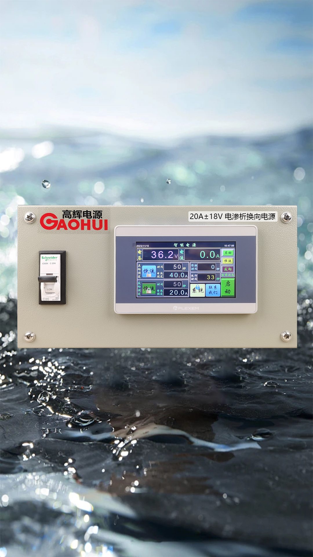
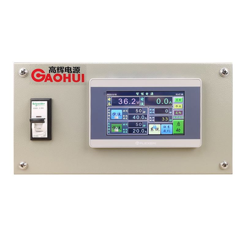
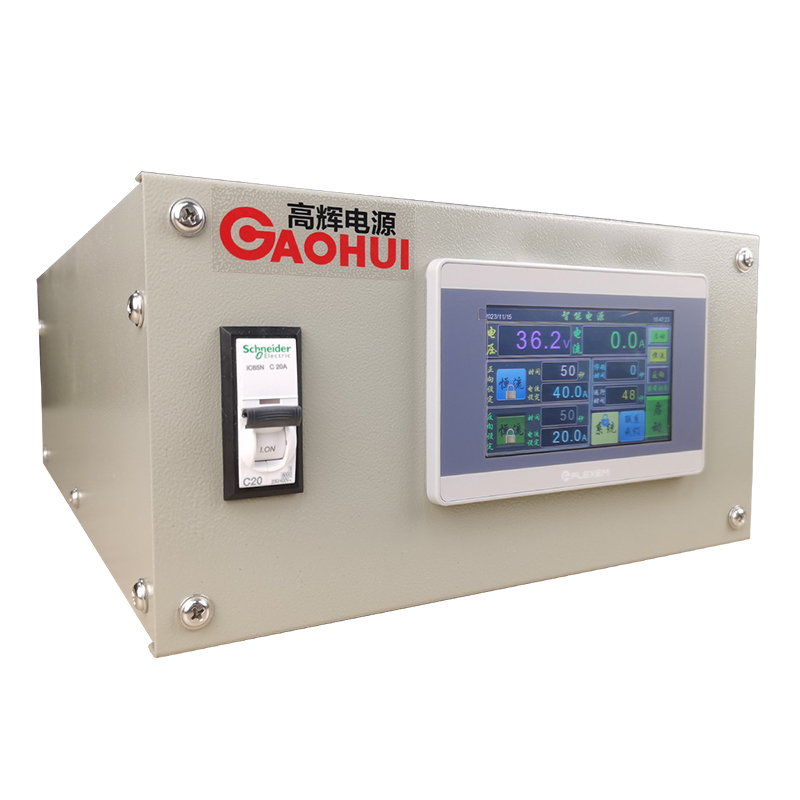
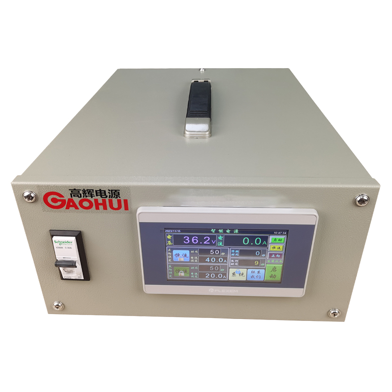
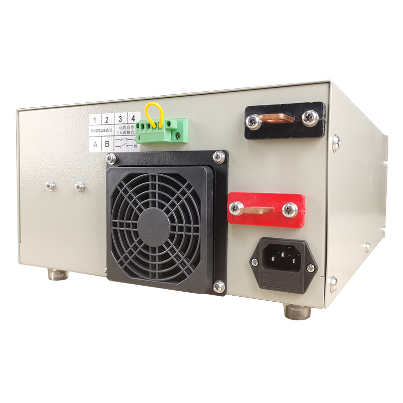
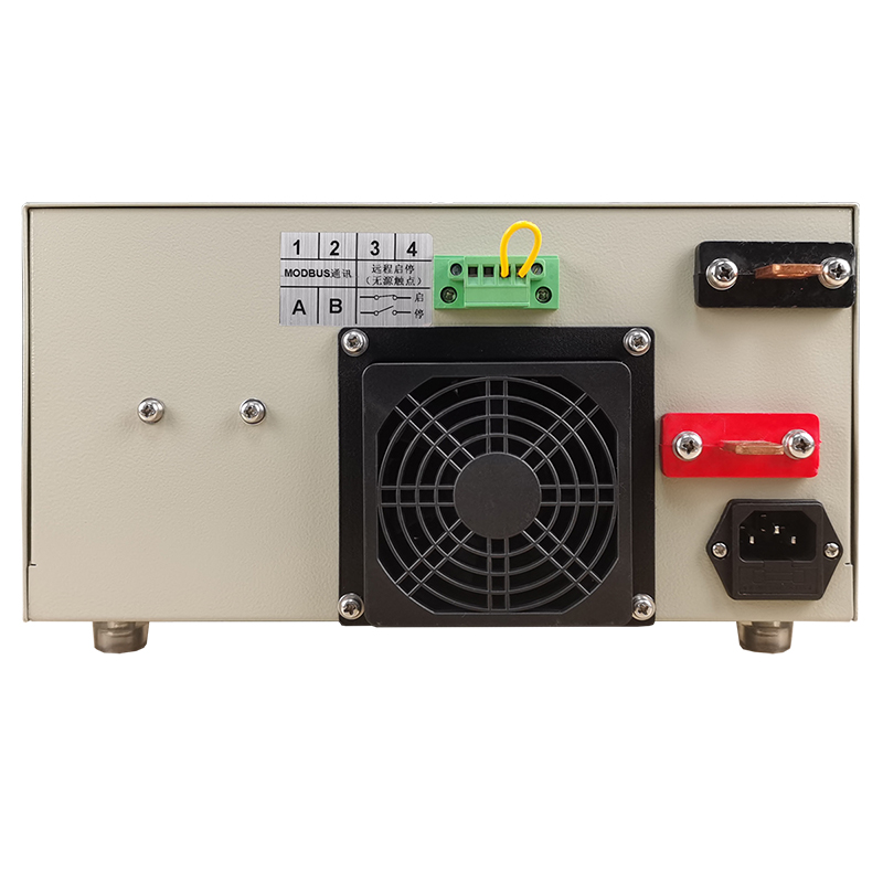
This compact 18V 20A air-cooled rectifier is a reference configuration for pilot EDR stacks and smaller modular systems. Its horizontal enclosure can be installed on a floor support or equipment rack close to the skid.
Key functions for EDR pilot systems
- Adjustable DC voltage and current: set the electrical load around stack area, feed conductivity and current-density target.
- Constant-current or constant-voltage operation: select the mode that matches commissioning data and stack behavior.
- Programmed polarity reversal: configure reversal sequence and transition behavior around the stack operating strategy.
- 4.3-inch local interface: view output values and adjust the working setpoint at the cabinet.
- Start/stop and alarm integration: coordinate output with flow, pressure, conductivity and skid safety signals.
- Forced-air cooling: support normal operation when airflow and clearance are provided.
These functions manage the electrical input and do not guarantee a fixed desalting rate, recovery or membrane-cleaning result.
Reference configuration
| Item | Reference configuration |
|---|---|
| Rated DC output | 0–18 V, 0–20 A |
| Rated DC power | 360 W |
| Typical AC input direction | Project-specific input confirmed during configuration |
| Cooling | Forced-air cooling |
| Local operation | 4.3-inch interface |
| Installation | Compact horizontal floor or rack support |
| Approximate enclosure | 275 × 360 × 160 mm |
| Approximate weight | 10 kg |
The reference rating does not define stack capacity. Final selection should check cell-pair count, active area, feed conductivity, flow, temperature and reversal strategy.
Connecting and selecting the supply
Connect the DC outputs to the stack busbars using conductors sized for continuous current and cable distance. Confirm flow, pressure, conductivity and any required interlocks before enabling output.
Select current from active membrane area and the target current density, then confirm total voltage across the complete stack at expected feed conditions. The reversal interval, dead time and auxiliary-valve sequence should follow the stack design and process controls.
See the electrochemical wastewater rectifier range for other configurations. For a larger EDR system, compare the 100A 300V automatic-reversing EDR rectifier.
Is reversal required for every electrodialysis stack?
No. Reversal belongs to EDR process design; a conventional electrodialysis stack may use fixed polarity.
Does 18V apply across every membrane pair?
No. Total output voltage is distributed across the stack. The electrical drawing is needed to check the voltage per cell pair.
Can the rectifier guarantee desalting performance?
No. Results depend on membrane condition, feed composition, flow, temperature, current density and complete-system design.
Request a stack review
Send the stack electrical drawing, cell-pair count, active area, feed conductivity range, flow, pilot current and voltage, AC input and control requirements. We can then confirm the electrical envelope and reversal functions for the system.